Switzerland: Thermally decoupling a goniometer

The goniometer
We’ve all done it. You spend several hours waiting for your sample to cool down to the correct experiment temperature, only to find that its orientation is out by a degree or two. Unfortunately, for the temperature range below 1K, current technology that moves the sample generates too much heat to maintain stable experiment temperature conditions. The sample heats up and you have to wait while you heat your sample back up again, re-position it and re-cool it, with your fingers doubly-crossed that it will be in the correct place this time. This is one guaranteed way of wasting precious beam-time.
If only there was a clever way to re-orientate the sample without causing a change to the sample environment conditions?
(N.B. A different, or additional, solution would be to speed up the cooling and re-warming time…which is exactly what researchers at STFC are trying to do. Watch this space for more details!)
Being able to manipulate the sample during the experiment, for example being able to measure at different orientations or align single crystalline samples at low temperatures or high magnetic fields, could also advance the analytical boundaries of techniques too.
The goniometer
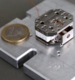
Step in SINE2020’s goniometer team. A goniometer, derived from the Greek words meaning angle (gõnia) and measure (metron), is a device that allows an object to be rotated to a precise angular position. Marek Bartkowiak and Ruchika Yadav from PSI have been involved in the design.
So what does this new design need to achieve? Well, in order to fix the issues in current experimental set-ups, the mechanical and thermal couplings (or connections) need to be addressed. This is represented in Figure 1.

Figure 1: Thermal and mechanical concept of the ULT sample stage. The part labelled goniometer consists of the moving parts including the piezo actuators.
1. The sample needs to be thermally coupled to the cooling device – the mixing chamber of the dilution refrigerator for this project – to get it to the correct temperature but not thermally coupled to the goniometer so that the sample does not gain heat when that moves.
2. The sample needs to be mechanically coupled securely to the goniometer so it changes position with it but does not move or fall off. But it must not, or only weakly, be mechanically coupled to the dilution refrigerator otherwise the sample will not move when needed.
3. The goniometer needs to be both thermally and mechanically coupled to another cooling device, a cryostat or warmer parts of the dilution refrigerator (e.g. IVC flange), that compensates for the heat generated during movement of the goniometer.
4. Per design, the mixing chamber of a dilution refrigerator and the IVC flange or the cryostat are only weakly coupled, thermally.
An important step of the project was to survey the project partners to find out the dimensions of dilution refrigerator inserts (the cooling device chosen for the project) on their instruments so that a developed design would be able to fit at all the European facilities. As you can imagine, there was a huge diversity on the geometrical values required as well as extra modifications needed for specific facilities.
A concept design
Using the survey results, three detailed concept designs for a measurement set-up incorporating a goniometer were proposed and discussed. It was determined that a Ø36 outer diameter would be required to suit all facilities. Some of the other considerations were:
- how to thermally isolate the sample. The team chose to use 3D printing as the process can make a complex design but with affordable materials. However, the low-temperature properties of commonly used 3D printing materials are not well known so PSI have started to characterize this information themselves.
- the goniometer itself. A 2-axis piezo goniometer with a single rotation point from the company Attocube was selected.

Figure 2: First proposed concept design, The goniometer is thermally and mechanically anchored to the IVC flange.
A prototype of one of the design concepts was manufactured and tested at PSI in Switzerland. It was discovered that magnetoresistance of the copper used to provide the thermal coupling to the sample and stiffness in Attocube’s commercially available goniometer caused a big issue.
In collaboration with the company, a second prototype is being built using a goniometer with capacitive rather than resistive encoders. Testing of this prototype will soon be carried out at PSI and ILL. Attocube are showing interest in distributing the final version as a commercial system.
Acknowledgements: Attocube and Marek Bartkowiak, PSI.
Back to The Road to the ESS
Other articles: PSI, Sample Environment, Fast-cooling furnaces


